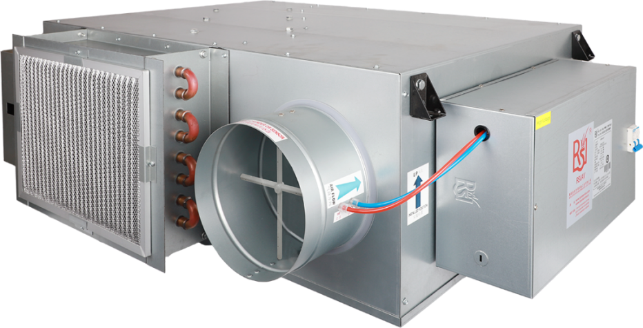
Fan-Powered Variable Air Volume Terminal Units Knowledge Sharing
The fan-powered variable air volume terminal, also classified as a throttling-type terminal, integrates a fan into the basic single-duct configuration. Based on the distinct arrangement between the fan and the primary air damper, it is categorized into series-type (FPS) and parallel-type (FPP).
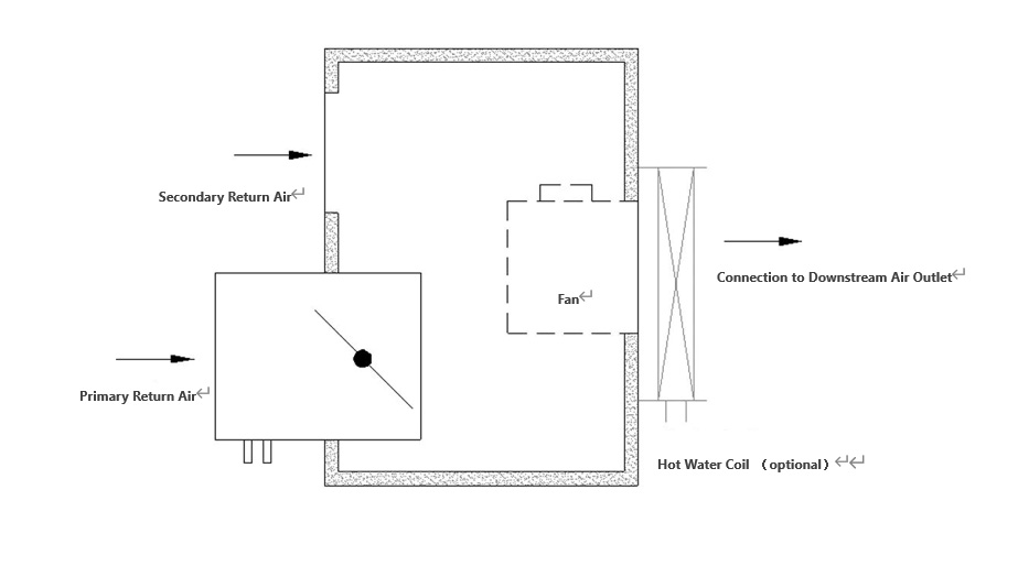
Series-type
The fan and the primary air damper are arranged in series, where the AHU-treated primary air passes through both the primary air damper and the fan. The fan operates continuously to maintain a constant supply airflow rate.

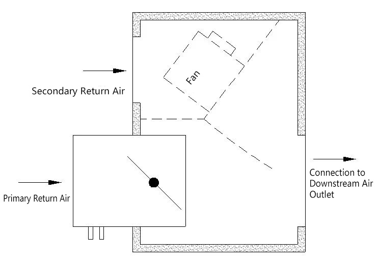
Parallel-type

Application and Characteristics
Series-Type (FPS)
1.The fan operates at a constant airflow rate, while the primary air volume is modulated according to room load variations. This configuration maintains a constant supply airflow rate but adjusts the supply air temperature, classifying it as a terminal device with variable temperature and fixed airflow.
2:Typical Applications:
(1) Spaces with low cooling loads and small amount of primary airflow (e.g., lobbies), where the minimum primary airflow cannot meet the required air change rate. The series fan-powered terminal ensures proper air distribution and prevents cold air dumping by enhancing airflow momentum.
(2) High downstream resistance scenarios, such as extended ductwork or reheat water coils installed downstream. The series fan-powered terminal overcomes resistance, reducing the required AHU fan static pressure and improving system energy efficiency.
(3) Low-temperature air supply systems (8–12°C). By mixing primary air with indoor return air, the series fan-powered terminal elevates the supply air temperature to prevent condensation on diffusers while meeting thermal comfort requirements.
Parallel-Type (FPP)
1.The fan typically operates only during reheat mode. When the fan is inactive, the terminal functions identically to a single-duct terminal, adjusting the primary airflow based on room load variations. If overcooling occurs, the fan is activated to draw room return air, thereby elevating the supply air temperature to prevent thermal discomfort.
2.Typical Applications:
(1) Spaces with high outside air requirements and significant load fluctuations (e.g., conference rooms). A high minimum primary airflow setting (mandated by ventilation needs) may cause overcooling during low occupancy or small cooling loads. The parallel fan-powered terminal addresses this by activating its fan to draw room return air, elevating the supply air temperature to prevent overcooling.
(1) Reheat systems with hot water coils. When the hot water coil is installed on the intake side of the parallel fan-powered terminal, it operates without increasing system resistance. This configuration minimizes static pressure losses, thereby reducing overall energy consumption compared to coils placed in the airflow path.
Motor and Speed Control Configuration
Standard configuration: a three-speed motor, a PCB power drive board, and a speed controller. By selecting different jumpers on the PCB board, the operating speed of the fan (high, medium, or low) can be changed.
The speed controller can be used to adjust the airflow and outlet static pressure of the fan based on the selected high, medium, or low speed of the motor, so as to match the requirements of the site's airflow and static pressure.

Optional for an ECM motor for quieter, energy-saving performance.
Product Model select
Series-Type (FPS)
1.Determine the maximum primary airflow based on the room's cooling/heating load requirements. Then, establish the minimum primary airflow (typically 30–40% of the design primary airflow) to meet criteria such as minimum outside air, heating needs, and air distribution effectiveness.
2.Calculate the fan airflow based on the required air changes per hour (ACH). Typically, the fan airflow is set at 1.0–1.3 times the maximum primary airflow.
3.Determine the required fan static pressure based on the calculated airflow and system resistance (e.g., ductwork, diffusers).
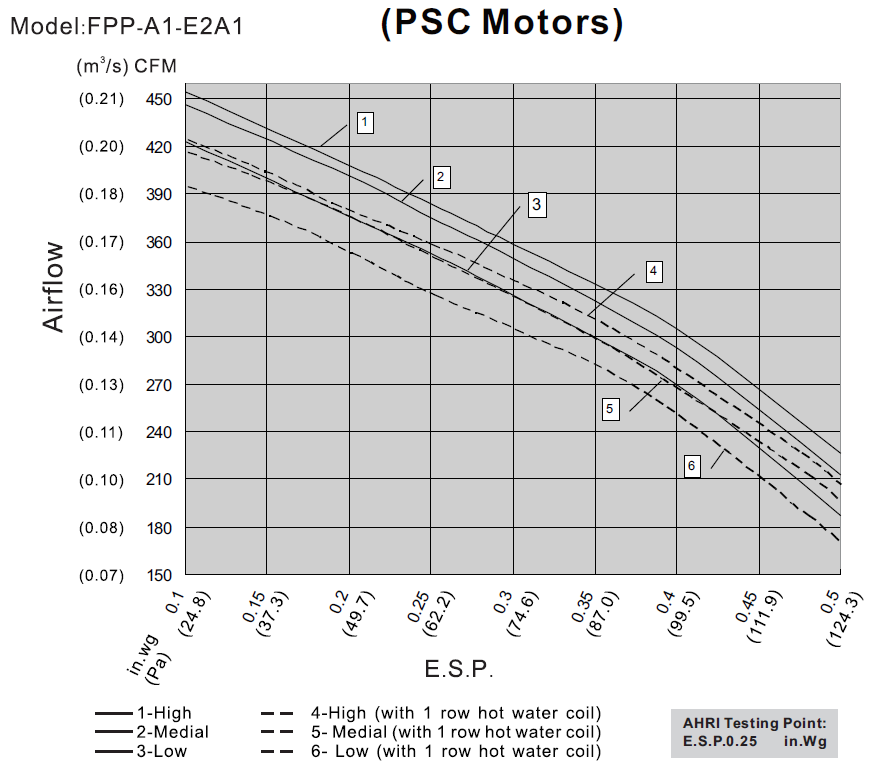
4.Select the appropriate model by referencing the fan performance curves of various models, ensuring the chosen unit meets both airflow and static pressure requirements.
Parallel-Type (FPP)
1.Determine the maximum primary airflow based on the room's cooling/heating load requirements. Then, establish the minimum primary airflow (typically 30–40% of the design primary airflow) to meet criteria such as minimum outdoor air, heating needs, and air distribution effectiveness.
2.Select the fan airflow based on either the minimum required recirculation airflow for the conditioned space or 50–80% of the design primary airflow (typically 60%).
3.Calculate the required fan static pressure based on the determined airflow and system resistance (e.g., ductwork, diffusers).
4.Select the appropriate model by referencing the fan performance curves of various models, ensuring the chosen unit meets both airflow and static pressure requirements.